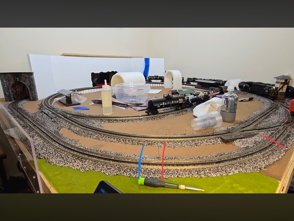
@Mark Boyce posted:

I just got on and I think Mike has one excellent point.  An engine can bridge between two blocks.  I have never fooled with this before.  Eric did a great job as always on his video, but doing it yourself can usually open a can of worms that the instructor left in the bait refrigerator. 

It’s almost always the case that there are examples only for some configurations, so it requires understanding the concepts so you can apply them to your particular design.

Mike/Mark. With the cuts on both sides of the switch area, that block is still powered. However, the signal wires are not connected to that block, they’re connect to the isolated blocks before and after that area. Therefore, the switch settings should have no affect on the signal lights the way Ken has things configured. He’s only using the signal for the outer tracks. Am I missing something?

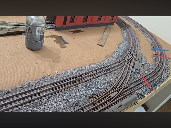
Ken, I just watched your video again. At the beginning the lights were green/red. As soon as you connected the first wire, the green lights turned red. That seems to indicate you connected it to a powered rail, not the rail between the cuts. Here are 2 photos that show where you might have made 2 of the cuts and where you connected the wires. The red lines are the cuts, the blue the connections. Are they right? Or should the blues and reds near each other be reversed in the photos?

IMG_0314


IMG_0307

Attachments

Images (2)
  • IMG_0314
  • IMG_0307

No. The red lines are the 4 cuts, wires are not soldered yet, I just touched the wires to the outside rail. The power rail is the middle black rail - I have done nothing at all to the power. Your blue marks are incorrect. I touch the outside rail after 1st cut and before last cut. Everything is done on the block, not outside of it. No activity outside of the 1st or 4th cut.

@DoubleDAZ here is a video of my setup. Hopefully it is a little clearer. And, you can see it is setup just like Atlas instructions. The only difference is I used the outside common(negative) rail instead of the inside common (negative) rail on a 3 rail o scale Atlas track. The 1st video from before where everything was green is the control sample - cuts made and no wires connected to track. Lights turn red once I connect one lead to rail, that is where the test began and the issue is found as the locomotive is not in the block and signals are red. Hence my problem.


https://youtu.be/37Zt9D16RCA?si=T2bx8xCehTtZ-5fi


@mike g. (Hope you are feeling better) and @Mark Boyce for your reference and to keep you in the loop if needed.

@mike g. I will do that, however this setup is not connected to switches at all. However, you did make me realize that I am connected through the power and negative buss for switches. I did just do what you said and it is still red. I am going to quickly run from the accessory buss directly instead. Maybe jumping the power and negative buss of the switches is the issue. I know, complicated reading, but trying to uncover all possibilities.

@mike g. It is connected properly, as it wont even light up if it is not connected properly. Atlas signal boards have a red light on the board which signifies it is connected properly. I just spent the last 30 minutes connecting to the direct accessory power and negative buss lines and it works exactly the same. This setup is straight from Atlas on how to power and also to let you know that it is powered properly, if no red light on board, it is wrong, if red light it is correct. I have no experience with other signals, other than the cheap one from a manufacturer from China. It was like $5 and operated like a $5 one....lol. Atlas is $90 I have been playing phone tag with Atlas support the last 3 days 🤬🤬🤬🤬 I am filming 4 of 5 days next week, so this could be a week from getting fixed unless someone has similar issue and know the minute mistake I am making. I am sure I have done something wrong that is so simple, because the board says everything is right and it does turn green with nothing on the track. So, it has to be something small.

Ok, I’m watching the video and see the cuts are correct (already figured that 🤣).

Then I got to the point where you were talking about the power. Let me start by saying you have 4 blocks. There is the main block around the rest of the layout, there is the block for signal 1, there is the block for the switches and there is the block for signal 2. The only difference is there is no power to the signal blocks until an engine enters the block.

The way you were explaining things isn’t quite right. At the point where you point to the rails, the inside and center rails are active, but the outside rail isn’t because the cuts isolate it. The trucks don’t connect power between the center and inside rail. When an engine passes the cut, it enters the signal 1 block. The "wheels" then connect power between the inside and outside rails. That is what activates the circuit turning the lights red.

Then you said the soldered wire lets you know it’s leaving the block, but that isn’t exactly correct. When the engine passes the other cut, it enters the switch block and power is lost to the signal circuit block. That’s what deactivates the circuit and the lights change to yellow and then green. The switches can be powered because they don’t affect the signal blocks. The outside rail is isolated by the cuts before and after the switches. Even if there’s power, that outside rail is not connected to the signal circuit.

Now, when the engine passes the next cut, it enters the signal 2 block and the wheels again connect power between the rails. That activates the circuit again and the lights change to red. I think that happens before the circuit finishes the yellow/green change.

Now, in the original video, when you attached the right wire the first time, the lights changed to red when the engine went through and eventually to yellow and green once the engine was quite a ways around the curve. The 2nd wire wasn’t attached at that point, so the circuit didn’t get activated again.

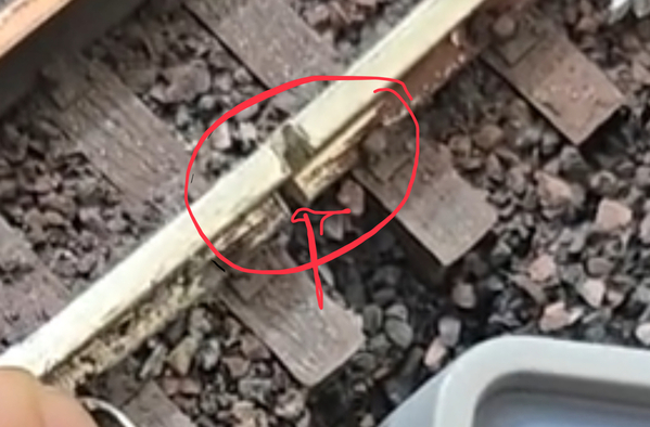
However, this is a closeup of the far right cut and it looks to me like the cut might not be clean, looks like to joiner might be touching. That would make the signal 2 block active all the time, so when the engine leaves the signal 1 block, the block is not isolated, so the lights is red as soon as the wire is attached.

I don’t know if that it, but it’s all I’ve got.
IMG_0315

Attachments

Images (1)
  • IMG_0315

Hey Ken here is an off the wall idea. The isolation sections I have done would stay red till the block was clear of all cars. If you power it up with nothing on the track and it is green. Take a box car or something with no power pickup and put it on the track and see what happens, place it outside the box and then just push it into the block section.

@mike g. Standby. @DoubleDAZ i see where you think the yellow etc happened that way, but actually in that test it did not. What happened was, after the trained passed the last "wire" the wire shook lose, so it appeared to work properly...lol. trust me, it did not. I do not have the din wires soldered yet I have been testing all this out before I do that. When I 1st started the test and videos I just laid the wires to on the rails side, but when the loco crosses it shakes it lose. Later in videos I tried to secure them better.

@DoubleDAZ I tested my earlier theory and did that. With nothing on the rails if I put the din wire on outside or inside rail the signal turns red. I was thinking maybe because I cut the outside that I needed the din to be inside. However, the results are exactly the same no matter where I put it, for 💩 and giggles I even did the power line and it too made lights turn red. No matter where I touch the din wire, the lights turn red. Standby. One thing I did not do in that test was see if it turns red with boxcar and wire.

Are you saying that with nothing on the track, the light turns red when you touch the rail between the 2 cuts? Come to think of it, you did connect the wire while the engine was already in the block, didn’t you? How did you connect power to the tracks to begin with? And where? I think you said you powered the outside rail, right?

Last edited by DoubleDAZ

Yes, i have power on the outside rail. I actually never connected, but ran a buss, for the inner as it was overkill for power and I also realized once I connected the transformer that because I did not run power to inner loop, locomotives ran perfectly fine conventional and app wise. So, the entire layout is on one arm of my MTH Z4000. I could do the same thing I am trying to do an isolate the inner loop but I do not believe it is needed. I can operate any conventional or newer app loco from 1 arm no matter where it is on the layout. I am not sure that is causing this issue, but I guess it could. But, my only pause on that being the case is, according to Atlas, a red light on signal control board means it is powered properly. Which again, lends me to believe I/we may be over-thinking this thing.

@DoubleDAZ there is power in the blocks and there has to be or the locomotives would not run. That is the whole purpose of isolation from my understanding. Nowhere have I read or seen there needs to be seperate power, just isolate with either plastic joiners or Eric's (and other's) method of cutting one of the rails to create a block. Supposedly the isolation let's the signal know there is a train there, but there is still normal power distribution. As nothing changes with the centerline and the ground comes from the non cut side and the metal wheels carries it across and the locomotive works as normal.   

@DoubleDAZ you mean power drops, I believe so, I would bet there are too as I added a bunch of drops as said before, i went overboard as it was as much about practice having never done this before. I did not need to run bus lines for this small layout, but I did to gain experience. I think I may have 4 or 5 drops in the block and as I said, it is probably something simple I did wrong. Because of the 4 switches, if I remember correctly I did a bunch of drops. And, that is a rather easy fix as it is an 80x80 layout and does not need the like 10+ drops i did....lol

Last edited by Dntbsillynow

Add Reply

Post
×
×
×
×
Link copied to your clipboard.
×
×