Originally Posted by pelago:

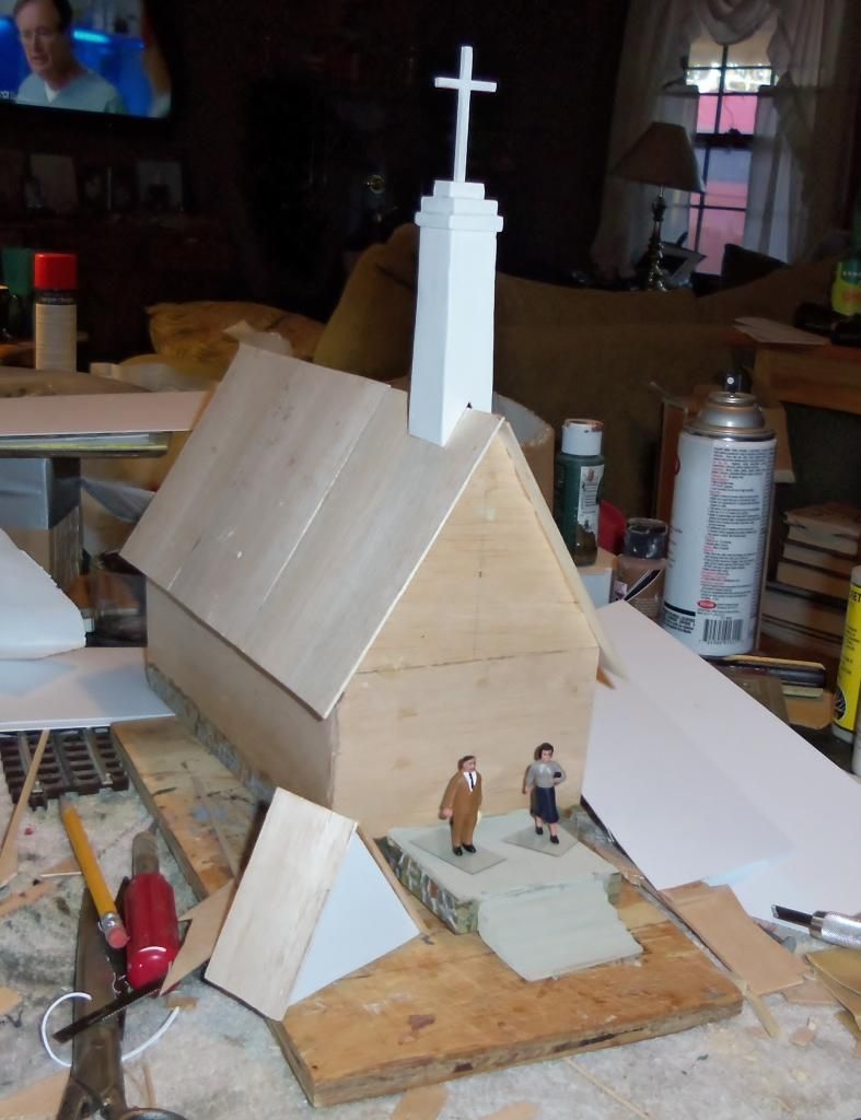
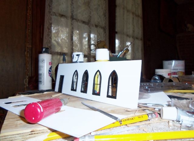
as i posted earlier I am building a small church, country style, has a steeple with a cross, and using GRANDT Line for windows and doors>  This is the window i am putting on each side, four to s aide.  These windows are recessed and i had to build a small jig to outline each window on the side and i used the jig to mark on (scale ) 6' centers  four windows to a side, front door is double and same deal had to build a cut out jig probably will have a access door on the side.

so far actual labor hours in project (actual sit down with wood or tools in hand)  10

got incredible cedar shingles for roof, can not wait to put them up, so so real looking, and the siding from evergreen is so so real also, it is conventional siding


now to figure out how to color the window paines, five of em, but think they have to have color

suggestions, all i can think is clear acetate and paint??

Pelago:


Tamiya paints makes a series of paints that are translucent. The colors are Clear Green, Clear Red, Clear Orange, Clear Yellow and Clear Blue. Their part numbers are 810XX (green is 81025). We use this with great success on stained glass windows of custom built churches. We use overhead projector transparencies for glass. On the transparency, you dab one color on with ample space between splotches for future colors. Let one color dry before applying the next in a similar fashion. The effect is GREAT!


Another trick we use if a client wants the image of a real stained glass window/s from their church is to take a digital photo of the window from the inside of the church on a sunny day, reduce the photos to the proper size for the window, print them, via color laser printer or copier on the overhead projector transparency and apply them to the window frames.


Though I do not have Tamiya paint on my web site, I can get it for you, but, my wholesaler looks as if he is low on stock. Many local hobby shops carry it, also.


Happy modeling and do share a photo of the finished church with us on the forum.

A bit of forgotten postwar vintage whistle tender lore:  The impeller bearing was so dry that the squeaking was drowning out the whistle!  So, I popped the top and applied some oil.  Now, the impeller bearing has a reservoir topped by a spring valve, as seen here:


GEDC1278

Putting oil on top of the valve does no good.  Using a needle oiler, push down on the spring-loaded ball and fill the reservoir:


GEDC1277

The whistle now roars merrily along, nice and loud and clear! 


Mitch

Attachments

Images (2)
  • GEDC1278
  • GEDC1277
Well, I tried for 3 hours to make my damaged turnouts work. One snapped immediately in half again so I'm done trying to fix it.
the other held well and I mounted the blue point under it.
but no matter what I did, even though the turnout points went the right way and looked to be pointing in the right direction, every car derailed and some just went the other way. I'm pretty sure I damaged one rail somehow I just can't see.
I'm done with trying to fix them. Out they'll come.
I'm going to buy two each replacements just to be sure I'll have one that'll work.
I came this far, just at the end of where I need to be ton run trains, to have new things happen to prevent it mo matter what I do.
I was so ticked last night. I keep hearing that this is supposed to be fun.
Hasn't happened yet.
Originally Posted by Randy Harrison:
Originally Posted by pelago:

as i posted earlier I am building a small church, country style, has a steeple with a cross, and using GRANDT Line for windows and doors>  This is the window i am putting on each side, four to s aide.  These windows are recessed and i had to build a small jig to outline each window on the side and i used the jig to mark on (scale ) 6' centers  four windows to a side, front door is double and same deal had to build a cut out jig probably will have a access door on the side.

so far actual labor hours in project (actual sit down with wood or tools in hand)  10

got incredible cedar shingles for roof, can not wait to put them up, so so real looking, and the siding from evergreen is so so real also, it is conventional siding


now to figure out how to color the window paines, five of em, but think they have to have color

suggestions, all i can think is clear acetate and paint??

Pelago:


Tamiya paints makes a series of paints that are translucent. The colors are Clear Green, Clear Red, Clear Orange, Clear Yellow and Clear Blue. Their part numbers are 810XX (green is 81025). We use this with great success on stained glass windows of custom built churches. We use overhead projector transparencies for glass. On the transparency, you dab one color on with ample space between splotches for future colors. Let one color dry before applying the next in a similar fashion. The effect is GREAT!


Another trick we use if a client wants the image of a real stained glass window/s from their church is to take a digital photo of the window from the inside of the church on a sunny day, reduce the photos to the proper size for the window, print them, via color laser printer or copier on the overhead projector transparency and apply them to the window frames.


Though I do not have Tamiya paint on my web site, I can get it for you, but, my wholesaler looks as if he is low on stock. Many local hobby shops carry it, also.


Happy modeling and do share a photo of the finished church with us on the forum.

thank so much,  all ext walls very close to being finished, one wall is done, the front door area done, the back is done and the other wall with four windows is cut and painted and waiting for final assembly.   windows were time consuming had to make sure jig was as close as i could get to the actual lip/rim of window, so that the final cut would enable the window to pop in,  a little glue and its there!

went thru quite apile of scrap siding to get it right,  and i have to admit, patience is the key,  a steel straight edge along the bottom of the windows showed perfect alignment


you can see the other wall laying on table with no windows in it and can see the windows drying

Originally Posted by pelago:
Originally Posted by Randy Harrison:
Originally Posted by pelago:


as i posted earlier I am building a small church, country style, has a steeple with a cross, and using GRANDT Line for windows and doors>  This is the window i am putting on each side, four to s aide.  These windows are recessed and i had to build a small jig to outline each window on the side and i used the jig to mark on (scale ) 6' centers  four windows to a side, front door is double and same deal had to build a cut out jig probably will have a access door on the side.

so far actual labor hours in project (actual sit down with wood or tools in hand)  10

got incredible cedar shingles for roof, can not wait to put them up, so so real looking, and the siding from evergreen is so so real also, it is conventional siding


now to figure out how to color the window paines, five of em, but think they have to have color

suggestions, all i can think is clear acetate and paint??

Pelago:


Tamiya paints makes a series of paints that are translucent. The colors are Clear Green, Clear Red, Clear Orange, Clear Yellow and Clear Blue. Their part numbers are 810XX (green is 81025). We use this with great success on stained glass windows of custom built churches. We use overhead projector transparencies for glass. On the transparency, you dab one color on with ample space between splotches for future colors. Let one color dry before applying the next in a similar fashion. The effect is GREAT!


Another trick we use if a client wants the image of a real stained glass window/s from their church is to take a digital photo of the window from the inside of the church on a sunny day, reduce the photos to the proper size for the window, print them, via color laser printer or copier on the overhead projector transparency and apply them to the window frames.


Though I do not have Tamiya paint on my web site, I can get it for you, but, my wholesaler looks as if he is low on stock. Many local hobby shops carry it, also.


Happy modeling and do share a photo of the finished church with us on the forum.
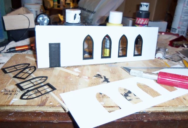
thank so much,  all ext walls very close to being finished, one wall is done, the front door area done, the back is done and the other wall with four windows is cut and painted and waiting for final assembly.   windows were time consuming had to make sure jig was as close as i could get to the actual lip/rim of window, so that the final cut would enable the window to pop in,  a little glue and its there!

went thru quite apile of scrap siding to get it right,  and i have to admit, patience is the key,  a steel straight edge along the bottom of the windows showed perfect alignment


you can see the other wall laying on table with no windows in it and can see the windows drying

Pelago:


Your progress photos look GREAT! Keep them coming.


Those particular Grandt Line windows work well with photos of real stained glass windows printed on overhead projector transparancy. Either photograph real windows yourself or get stained glass window photos off of the internet. there are hundreds out there.

"Those particular Grandt Line windows work well with photos of real stained glass windows printed on overhead projector transparancy. Either photograph real windows yourself or get stained glass window photos off of the internet. there are hundreds out there"

considered that, even considered trying to cut out color acetate and putting it in the five frames,  but the width of one is 1/32" wide,  just the thought of me trying that almost put missiles in the air from frustration of screwing it up,  would be nice though

i even have a window design program, but none of the windows are in the catalog.  while wandering around michaels i found some gold velum 8X11 sheets f0r 25 cents each, then a pale green, a foggy white, and a pale i mean pale yellow  bought a sheet of each

got home and played with some color, the church will be lighted from inside and yeah colored glass would be a eye catcher,  tried some red, some pale green, opaque white then i put a piece of gold in there and wow, it really caught my eye,  said to my wife look at this and held it up at first no comment then she said hold it up again, and said, that really sets off the black trim and white siding,  it looks good, with soft light behind it

so the plan is gold velum on 8 arched windows,  opaque white on entrance,  a overhead light on a small porch in the front and a area light on telephone pole in back of church with trees and small picnic table . siding is white, trim black and roof (well just not sure, i have cedar shingles on my garage and on the railroad room and it will be that color)

that window design program works pretty good especially if the bldg is in the software there is a photo of my bride in the bathtub  over Granatos Grocery, one of these days she will see it,  perfect scale, i mean perfect scale and proportions

Last edited by pelago

Historical Note:  For those of you who use various and sundry parts from GRANDT LINE in Concord, CA ...  Here is a rare photo taken of the company Founder, "Cliff Grandt" ..

Photo was taken in the 1940's at the old Eastbay Model Engineers Society club in Emeryville, CA (Oakland) ...  Thought you'd all like to put a name to a face !

Cheers.


KRK

grandt_cliff

Attachments

Images (1)
  • grandt_cliff

Since I was using my Marx store layout at the train show yesterday, I figured it was only fair to give the Marx train that came with it a little exercise today! 


A little oiling, a little cleaning and a few drops of smoke fluid later, this perky 666 was cheerfully grinding its way around my outer oval, easily pulling its consist! 


GEDC1279

Mitch


Attachments

Images (1)
  • GEDC1279
Originally Posted by keyrouteken:

Historical Note:  For those of you who use various and sundry parts from GRANDT LINE in Concord, CA ...  Here is a rare photo taken of the company Founder, "Cliff Grandt" ..

Photo was taken in the 1940's at the old Eastbay Model Engineers Society club in Emeryville, CA (Oakland) ...  Thought you'd all like to put a name to a face !

Cheers.


KRK

grandt_cliff

talk agout reasonable prices!  i picked up 8 windows, one entry door, two 5 panel doors with frames.  less than 15.00 including shipping, and enclosed was a super catalog, sure internet shopping is great, but me i like to hold the catalog in my hand, that way i can quick refer to pieces and parts

SIMPLE ENOUGH STATEMENT,  GOOD PRODUCT, FAIR PRICES,  SHIPS REASONABLY FAST.  I LIKE DOING BUSINESS WITH THE COMPANY.

They have broadened my project list,  farm windmill, water tower, pieces and parts for 'downtown', like the manhole covers


about my church, was commenting about lights and Tammy my wife  said, don't "northern up the church"  small rural churches were usually poor. but were the center of the community, up to including a cemetery, you were born in the church, raised in the church, went to Boy Scouts in the basement, might have even got your first kiss at some youth group event, you were married in your church, baptized your chidlren, and yes died in the same church.  and it is probably as poor as it was the day you were born so don't Northern it up with chandoleers, and bit out door lights, keep it simple 

Finally started laying track again! This is the first new track work since before Thanksgiving. I got the entire Wye constructed and the curved switch leading to the passenger station siding. Tomorrow I'll finish the straights on the inside loop and start laying the last of 4 curve sections. Pictures to follow.


Gilly

Originally Posted by keyrouteken:

Historical Note:  For those of you who use various and sundry parts from GRANDT LINE in Concord, CA ...  Here is a rare photo taken of the company Founder, "Cliff Grandt" ..

Photo was taken in the 1940's at the old Eastbay Model Engineers Society club in Emeryville, CA (Oakland) ...  Thought you'd all like to put a name to a face !

Cheers.


KRK

grandt_cliff

Ken,

Thanks for the photo of Cliff Grandt.

Grandt Line sold me a large quanity of windows, still on the sprue, unpackaged, that

I  haven't yet used because the photos of the stamp mill I want to model are purported to be locked in a vault, and unpublished.   GL was accommodating.  I have seen a few copies of those stamp mill photos,  but not enough to model from. Today I drove through a blizzard (they don't call us train NUTS, for nothing) to a show hoping a parts guy would show up. Nope. I need better choices of pilot trucks for this kitbash.  I did solder on the buffer beam and will later look at what else, in addition to the feed water heater, needs to go on the pilot plate. Luckily, it looks like less on the earlier version

i am trying to copy ("model" is the wrong term, as I elected not to grind off the

third dome, so "approximation" might be the right term).

Tonight I continued by trying to get the pilot (cowcatcher) to fit and work with the

factory coupler set up (everything to date has been designed around that, and that

is a problem).  I am now test fitting a Weaver plastic "lobster claw" as it has less

vertical width and may clear the pilot opening.  Would have to design in and add springs for horizontal return to center, and add a mounting block to the pilot

plate/original coupler mounting posts.  Should hold everything until I can get some

different pilot trucks.

Yesterday and today it is train running. My challenge now is to come up with a control panel for the switches and uncoupling tracks and figure out where or how I can incorporate it into the table where the transformers are so I can run all the wires to them. Big hurdle for me because I am not a carpenter. I can measure three times and still not cut the wood right......Paul

Originally Posted by paul 2:

Yesterday and today it is train running. My challenge now is to come up with a control panel for the switches and uncoupling tracks and figure out where or how I can incorporate it into the table where the transformers are so I can run all the wires to them. Big hurdle for me because I am not a carpenter. I can measure three times and still not cut the wood right......Paul

ah-haaaaaaaaaaaaaaaaaaaaah

found your error,  "measure twice cut once"  that third time did you in

Originally Posted by paul 2:

Yesterday and today it is train running. My challenge now is to come up with a control panel for the switches and uncoupling tracks and figure out where or how I can incorporate it into the table where the transformers are so I can run all the wires to them. Big hurdle for me because I am not a carpenter. I can measure three times and still not cut the wood right......Paul

Hi Paul,

I can show you what I did and you may get an idea from that. I also am not very good building things, but I am a perfectionist. So, my result was fantastic on my scale but probably only child-like for someone who knows what they are doing.

So, I went to home depot and bought the cheapest end of a piece of 3/16" fibre board with one side smooth to provide a finished looking outside. I also picked up some right-angled brackets and a tube of No-More-Nails. I also used 2 coats of some dark brown stain I had around plus 2 coats of matte varathane for protection. My panel is 5 1/2" wide and 16 1/2" long. I left one end open for ease in connecting wires and nobody can see that side anyway. My wiring/ cross-connect panel is directly under my layout from the panel so it was easy to run the wires straight up. Also I didn't drill any holes in the 1" MDF layout base as my layout is small and I was afraid to make a big mistake. From the attached pictures you can see there is a lot of stuff in a small place.

Assembling the box is easy. Cut the pieces for sides based on how high and long you want it. Place the brackets along the top edge and mark them out in pencil. Fill in the pencil are with no more nails and let it dry. Etc., Etc. for the other sides and top. Its quite sturdy and light. Hope this helps you. Best of luck.

Cheers,

Eric.

IMG_20150228_145522

IMG_20150228_145603

IMG_20150302_093856

IMG_20150302_094708

IMG_20150302_095021

Attachments

Images (5)
  • IMG_20150228_145522: Layout with Control Panel
  • IMG_20150228_145603: Overhead
  • IMG_20150302_093856: Side view showing on-edge of table location with wiring from below
  • IMG_20150302_094708: inside brackets and no-more-nails glue
  • IMG_20150302_095021: open end view showing toggle and top-side joint construction
Originally Posted by Ericlinda:
Originally Posted by paul 2:

Yesterday and today it is train running. My challenge now is to come up with a control panel for the switches and uncoupling tracks and figure out where or how I can incorporate it into the table where the transformers are so I can run all the wires to them. Big hurdle for me because I am not a carpenter. I can measure three times and still not cut the wood right......Paul

Hi Paul,

I can show you what I did and you may get an idea from that. I also am not very good building things, but I am a perfectionist. So, my result was fantastic on my scale but probably only child-like for someone who knows what they are doing.

So, I went to home depot and bought the cheapest end of a piece of 3/16" fibre board with one side smooth to provide a finished looking outside. I also picked up some right-angled brackets and a tube of No-More-Nails. I also used 2 coats of some dark brown stain I had around plus 2 coats of matte varathane for protection. My panel is 5 1/2" wide and 16 1/2" long. I left one end open for ease in connecting wires and nobody can see that side anyway. My wiring/ cross-connect panel is directly under my layout from the panel so it was easy to run the wires straight up. Also I didn't drill any holes in the 1" MDF layout base as my layout is small and I was afraid to make a big mistake. From the attached pictures you can see there is a lot of stuff in a small place.

Assembling the box is easy. Cut the pieces for sides based on how high and long you want it. Place the brackets along the top edge and mark them out in pencil. Fill in the pencil are with no more nails and let it dry. Etc., Etc. for the other sides and top. Its quite sturdy and light. Hope this helps you. Best of luck.

Cheers,

Eric.

IMG_20150228_145522

IMG_20150228_145603

IMG_20150302_093856

IMG_20150302_094708

IMG_20150302_095021

Great idea, Eric!  I am like you and Paul, I am a perfectionist, but have always lacked the dexterity to cut where I have measured three times, or it ends up crooked.  I also lack the funds for a nice table saw or other tools that help for accurate cuts.  Thank you for the example!

I put the pulls on the end of the op rods for the blue points to operate my turnouts (all but the two which are broken and will be replaced, of course). I decided to paint them red-white to indicate main and diverging directions like a switch stand on a real railroad, so you only have to look at how far out the pull is and the color to see if it's set for the main or siding:

I completed laying FasTrack for my rendition of Ken Hoganson's plan in Run 275 of OGR.  I still have to prove I have continuity on the last portion, but had to quit for the evening.  I want to finish the track and power this week, since I will be having surgery on my right hand next Monday.  The left hand could have stood to be a little stronger from therapy after its surgery, but I managed. I will post a photo or two after I have cleaned up the hodge podge of scenic items and rolling stock strewn about the open spaces. 

Successfully installed LED's in three of my PW style 15" passenger cars previously repainted in GM&O Abraham Lincoln livery.  Will do the observation car later tonight or tomorrow.  The obs car is a bit more complicated since it already has Tomar Industry drumhead and associated wiring, including an incandescent bulb as part of the drumhead wiring.  I'll probably call Tomar in the a.m. and see about eliminating the bulb.  Still undecided about lighting the baggage car.

Busy day today. I thought it would be a good idea to get the Ford Plant wired before starting to lay track at Hiawatha below.


This was the hard part. I got about 2/3 of the way down the line. I should finish the wiring tomorrow if my hands aren't too sore.


IMG_4952

I got a good start on Hiawatha, but I may be stuck for a few days. I'm almost out of track pins. Got some coming from Trainz. Then I'm almost out of track, so I ordered another case from Train World. Then I need a 45 degree crossing, gonna check the LHS, otherwise I'll have to go straight to Ross. Giving the forum sponsors a workout.


IMG_4949

This is the part of the layout I wanted to have done first so I could play,and it ended up being almost the very last.


IMG_4950

Attachments

Images (3)
  • IMG_4952
  • IMG_4949
  • IMG_4950

I've been busy over the last weeks getting my second mainline operational.  I'm happy to say that the line is now operational...... thanks to my good friend Randy Harrison lending a much needed helping hand with cutting and bending Gargraves track.  He always seems to have great ideas too!


I spent yesterday afternoon screwing down track and fixing a turnout.  I also ran trains yesterday as well ... which was big fun!!!  Trying out several locos through my new junction turnouts ( to great success )  and then just running whatever I wanted.  Finally I was fast running a Williams scale B&O Hudson with scale express and passenger cars on the outer loops.  By contrast on the inner loop,  I ran a 10 car, super slow, colorful beer train with a FM Trainmaster ( by Williams ) on the point and an American Association of Railroads caboose ( by RMT ) on the rear.  Quite an array of color!


Its now great to have 3 trains running simultaneously .... 2 on the lower deck ( inner and outer loops ) and one on the Mountain Division.  


My Z 4000 is at MTH being repaired so I now power the layout with two old Lionel ZWs and this works well.  MTH has a several month back up on repairs.  I am going to install inline fuses to the ZWs so I can run my MTH and Lionel TMCC locos without them being fried, due to voltage spikes.  At the moment i'm only running Williams and Post War locos.


Today, I created a projection of what my engine service facility will eventually look like.  Doing this sort of projected moch up and photographing it allows me to see/imagine what is needed to enhance this area of my layout.  What you will see in the accompanying photo is in no way what I see as being the finished product..... however this photo serves my imagination as a basis on which to create my ultimate engine servicing facility scene.  


This hobby is a duality of great frustration and super fun and satisfaction, as I'm sure many of you have experienced as well.  Sometimes when working on a layout I can become extremely frustrated and loose my patience ...  and then there are those times when everything just fits and flows all together.  I guess working on a layout is pretty much a mirror of life itself


Well, thats the latest on my progress with the Free State Junction Railway.  

Attachments

Images (1)
  • Engine Service Patsburg

Today I found a control panel I made up years ago. I am going to see if it will be big enough to put a track plan on along with the switch controllers and uncoupling controllers. Then if it works I'll have to figure out a place I can put it. I also decided to replace some small one by four pieces I had holding up the upper mainline in spots. Replacing them with some 3/4 inch dowel which does not look as bad...................Paul

Dropped a 15 amp breaker from O'Reilly's Auto Parts into my new/old ZW:


GEDC1281

As you can see, the old breaker makes a dandy bracket for holding the new breaker in place (once you tape over the lug connectors, of course).


At full power on the D-U terminals, the new breaker trips at the 4-6 second mark, which should be fine for everyday use.  Experts do recommend using individual breakers for each track, as well.  I tested my old Marx breaker for this, and it did splendidly! 


GEDC1282

Mitch

Attachments

Images (2)
  • GEDC1281
  • GEDC1282

Finally got the delivery of my DDA40X Crescent Locomotive Works repaired for me after a delay while I vacationed in the Hotel 'd Hospital over the weekend with a dangerous bacteria ... probably caught working on the layout, ... like all the other problems I encounter in that venue.  lol!

We'll get it up on the layout tonight and enjoy a run of the "Wilmar Engineering Special".

Took care of some DL (Disabled List) items from the last train show, as I took another snow day today...


As it turned out, I had to sideline the Gi-raffe GG1, since some inside bosses of the Lionel shell were hitting one of the Williams flywheel: 


GEDC1288

As a temporary measure, the factory Pennsy shell will be wearing Giraffe Express heralds for the time being:


GEDC1289

If anyone has a spare Lionel GG-1 chassis for sale, please let me know! 


One of the gi-raffe cars suffered a broken actuator arm in a wreck:


GEDC1284

A little bit of Testor's Cement and a patch of Evergreen styrene put things to rights.


GEDC1285

The GX-1 (Gi-raffe Express 1) was sidelined with a broken motor wire solder joint:


 GEDC1287

I resoldered all the motor wires just to be sure. 


Incidentally, note a couple of mods I did:  The headlights are grain of wheat jobs mounted in aluminum tubing slipped over the headlight lenses.    Also, the speaker has a resonator made from the base of a plastic Dixie cup... 


My Pennsy 2025 has been sidelined with a dirty commutator plate since last August.  So, I did a quick cleanup, added new brushes, oiled the tender whistle (see my earlier posting on that) and now the consist cheerfully chuggeth along: 


GEDC1290

With Princess Daphne's caboose...er, Princess Daphne's rear bringing up...er...oh, well, you get the idea. 


GEDC1291

Mitch

Attachments

Images (7)
  • GEDC1284
  • GEDC1285
  • GEDC1287
  • GEDC1288
  • GEDC1289
  • GEDC1290
  • GEDC1291

Today was a good day to work on the layout since it snowed all day in NJ.  I decided to install the Lionel Hobo Tower behind the centerfield fence on my hidden under-the-table layout.  This little vignette works well for me because I have limited space where I have set up my main layout (not shown) i have utilized the unused space under my trainyard (shown) which connects through a wall to the main layout.  When I am done, the hidden under-the-Table vignette folds up and is hidden by the walnut stained door......enough talk, here are the pictures of my continuing under-the-table project.


Took my Weaver GP-38-2 dummy unit back apart many times today to get the ERR GP7/9 sound system to work,  something to do with the data wire between the sound unit and ERR dummy unit. The sound would work with the hood off and stop with the hood on, then work with the hood on and not work with the screws back in to the hood.


Now all systems are working as they should,  but have not hauled the engine in the train around the layout.  The GP-38-2 sounds great, I hope it stays working.

Last edited by CBS072

I've been laying track for the last two days. It was kind of slow going yesterday because I ran out of Gargraves pins, and had to get into my stash of ancient brass pins, which all had to be cleaned one at a time. If only I had gone down to the mailbox yesterday, I could have avoided all that. This morning I discovered the pins I had ordered from Trainz. Oh well.


Hiawatha is coming along nicely. All of the track in this shot is screwed down, except the two switches at the bottom.


IMG_4955

There's still a couple industrial tracks and a small yard at the far end that need to be done, but I'm out of track. I'm expecting a case tomorrow. This could be the LAST case!   It's gonna be close.


IMG_4957

The LHS actually had that Ross 45 degree crossing. It's always a strange feeling cutting a brand new piece of track. I'm committed now, can't return it.


IMG_4958

To see the real Hiawatha Avenue milling district click here.


Part of me wants to start getting to scenery in this aisle, but the other part of me says the upper deck wiring is a bigger priority.

Attachments

Images (3)
  • IMG_4955
  • IMG_4957
  • IMG_4958
Last edited by Big_Boy_4005

Add Reply

Post
×
×
×
×
Link copied to your clipboard.
×
×