
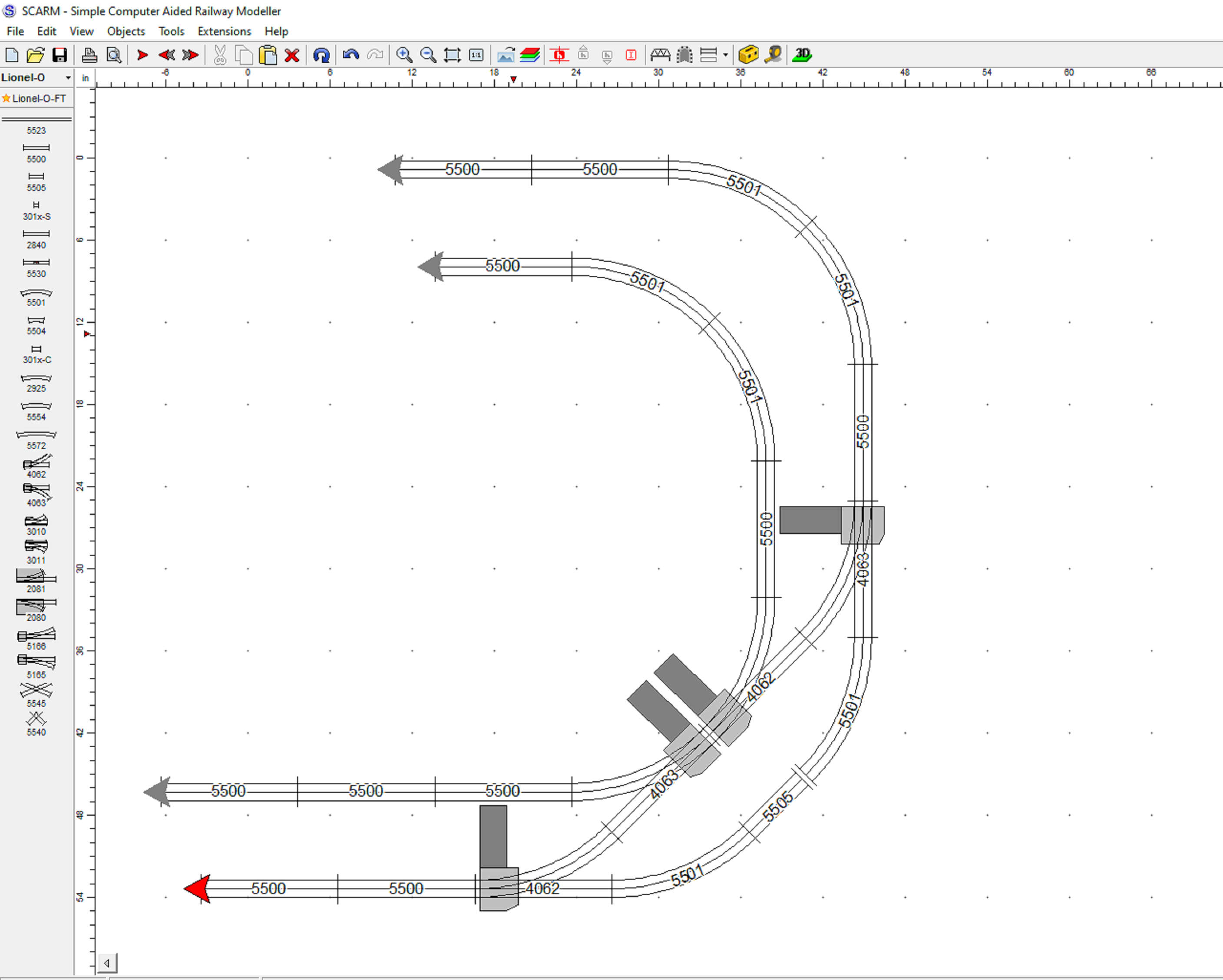
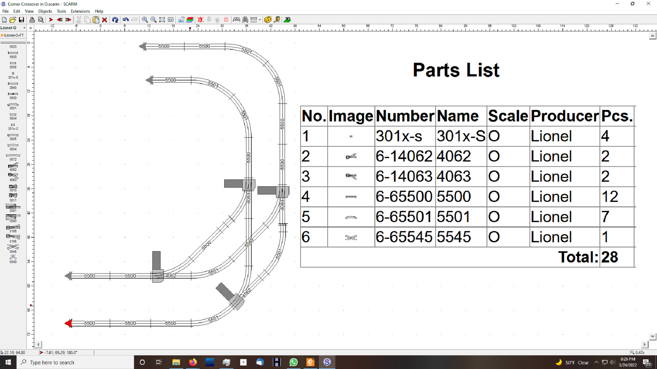
Newby needing assistance/reference recommendations: I am building a Conventionally Controlled, PW, O-Guage, 3-rail, tubular track (Lionel 0-31) layout (5'X10'), see below sketch. There are two, concentric main line loops connected via four (4) turnouts, connected back-to-back, forming a "bell" curve shape between the two mains. I plan to use a PW Lionel ZW transformer to power the two mains (A-U and D-U terminals) with separate "hot" busses. Accessories, lights and turnouts will have separate "hot" busses powered by a combination of other transformers and the constant voltage terminals on the ZW. I will be wiring in bi-directional, TVS diodes and fast circuit breakers as described elsewhere in the Forum. Can you kindly recommend a wiring book or books, that will guide me thru the wiring and insulating pin locations in of this conventionally controlled layout? I am most confused about how to wire/insulate the four (4) turnouts separating the two mains, while maintaining the anti-derailing feature of the turnouts. The recent wiring books I have looked at seem to focus on digital control methods (MTH or Lionel) instead of the conventional methods that I wish to run. Many thanks.SCARM No 10 21Feb2023 BACKUP

Attachments

Images (1)
  • SCARM No 10 21Feb2023 BACKUP
Original Post

Replies sorted oldest to newest

U.P.,

I can't think of a book I've seen that covers this situation, so I'll take a stab at it here.

I'm making the assumption that the interior loop we see (complex, with reversing loops and a siding built in, pictured in green below) and the exterior loop (simple, pictured in orange below) are the two loops you refer to.  If this is the case, then the fibre (plastic) pins that are important to you, in order to run these two loops independently, need to be in the center rail, isolating the 'hot' leads, 'A' and 'D', from the two transformer circuits, and keeping the two from fighting each other.  They would be inserted in the center rail at these locations (red and blue arrows):

All other plastic pins, for instance those for maintaining anti-derailing functionality in the switches are already, or should already be, found in the outside rails of the switches, as they were positioned coming from the factory. No need to touch these.

Two lock-ons, at a minimum, are necessary, one somewhere on the exterior loop and the other somewhere on the interior loop.  The outside rail connection for each of these lockons connects to 'U' (2 wires).  The center rail connection for the lockon on the inside loop goes to 'A' and for the outside to 'D', or vice-versa if you prefer.

One last point, if you're trying to move a train from the outside loop to the inside loop, or the inside loop to the outside loop, make sure that the throttles for the two loops are set to approximately the same position during the transition, or sparks will fly underneath as the pickup rollers for the locomotive and any lighted cars go through.

Mike

Attachments

Images (1)
  • mceclip1
Last edited by Mellow Hudson Mike

Blue wire is optional but helps preserve common connection circuit for non derailing.

Fiber pins are red, steel pins are yellow.  Green rails are non-derailing trip/trigger rails, orange rails are the common rails needed for non-derailing to work properly... their connection is made through the internal switch structure as they are otherwise completely isolated by the fiber pins.

Controllers are connected in the usual manner.

Last edited by ADCX Rob

Not a wiring suggestion but rather a track plan suggestion.  I've seen many a track design similar to what you showed to us and never cared for it.

Your inner loop is the point of my interest for 2 reasons:

1. the 2 switches on the extreme left create a path that is nearly identical to the path if no switches were involved.  Seems curious to me but I don't know your intentions either.

2. You really don't have a 'reversing loop'.  Trace thru it and you'll see this: If you start off running clockwise you can reverse the direction.  Once it's reversed you can't "re-reverse" it - you're stuck going counter-clockwise.

Again, I don't know your intentions but thought I would offer my thoughts.

hope you don't take offense.

walt

Sorry for my delayed response. We just had power restored from an outage due to very wet snow storm here in Upstate NY.

Mike and Rob: Many thanks. You diagnosed and solved my issue beautifully and very clearly! Thanks also for the advice on the throttle control. I'll be careful to train (pun intended) my engineers (8 and 10 yrs) how to manage the throttle as they traverse from one main line to the other!

Walt: My thinking on the additional inner loop was a storage siding or a track for another operating accessory. The layout theme is more of a toy train vs. prototype operation.  I may , however, be guilty of placing too much track on the layout. If the layout gets too crowded I will definitely consider eliminating this redundancy.  I have been tracing over the reversing loop and I believe it can work as follows.... If you are running counter-clockwise on the inner loop, the train can reverse and back down the diagonal side of the reversing loop from the top, passing totally thru the diverging path of the turnout at the bottom of the diagonal, then reverse again and proceed straight thru the same switch in a clockwise direction around the inner loop. I guess it kind of works like a "Y".  Believe me, I was agonizing with this very issue for quite a while - not very good at puzzles! Thanks for your observations. If you have any two (2) main layout ideas that fit on a 5x10 platform, I would enjoy seeing them. I am looking for a design that will hold the interest of grandchildren.

Thanks again to all for your courteous and timely responses.

UP Boilermaker (My grandfather's job with the UP in Cheyenne)

@walt rapp posted:

Not a wiring suggestion but rather a track plan suggestion...

..am looking for a design that will hold the interest of grandchildren.

The only change I would make is to eliminate the "ESS" S curves in the crossover switches for smoother running.

OR, using a little creativity and an interesting track plan...

Or:

Last edited by ADCX Rob

I disagree with your comment, not to be a pest or anything.  You wrote:

passing totally thru the diverging path of the turnout at the bottom of the diagonal, then reverse again and proceed straight thru the same switch in a clockwise direction around the inner loop.

I for the life of me can't see how the train could 'reverse again'.  You would need 2 lefts to make it reverse again.

I like Rob's track suggestions.

walt

Add Reply

Post

OGR Publishing, Inc., 1310 Eastside Centre Ct, Ste 6, Mountain Home, AR 72653
800-980-OGRR (6477)
www.ogaugerr.com

×
×
×
×
Link copied to your clipboard.
×
×