Hey Gang,


Update: 7/8/15 - The Cruise Commander supplies 12V DC for lights.


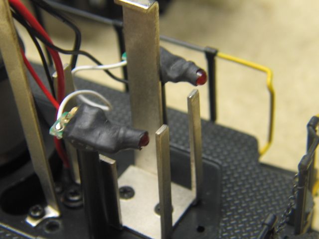
Does anyone know what the voltage output is of the ERR Cruise Commander for lighting? I'll be calling ERR in the morning, but am hoping a night owl might be up who can answer.  I'm replacing the marker lights that won't illuminate on the current coming from the Cruise Commander. My guess is that the current required to run the marker lights is too low. (The headlights work fine.) 


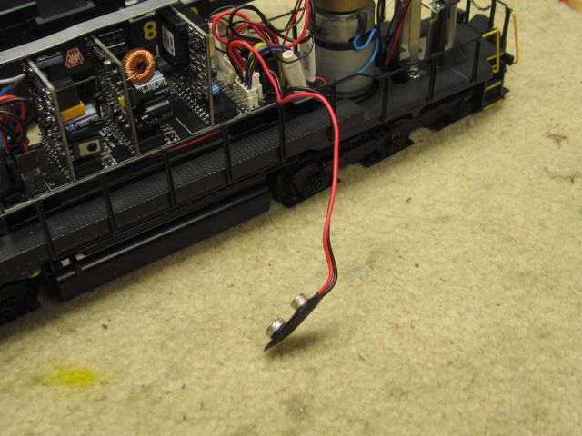
Backstory: I have an AtlasO SD35 that has been giving me fits for some time. It put on a nice light show with all the sparking. When it took the through route of a turnout, the middle wheelset of each truck arced to the middle rail of the diverging route. At slower speeds, it would short and turn off. I've swapped wheelsets and pickup rollers, and gave it a thorough cleaning and lube job, but the problem persisted. The other night, I decided that I would gut it and use it as a dummy. After removing the old board, I thought what the heck and threw in an ERR Cruise Commander I have for another project just to see what would happen. I connected only the power and motors and programmed it for 100 speed steps. I turned the throttle...and it crept around the layout on speed step 1!!! The light show is gone and it runs smooth as silk!

Last edited by ChessieFan72
Original Post

Replies sorted oldest to newest

The lighting outputs of the R4LC, which is where the light outputs originate are half-wave track power in command, and full-wave track power in conventional operation.  In command, the resultant half-wave DC is negative in respect to frame ground.


If you're trying to compute what voltage you have, figure on 9 volts in command, which is the half-wave 18 volts from track power.  If you are using LED's, you'll need series resistors and make sure the positive terminal goes to frame ground.  For markers, I typically use two red or green LED's in series with a 1K resistor, it does a good job and is easy on the LED's.


True, but the RMS value doesn't really tell the whole story here.  If you look at the heating value of the half-wave signal, it isn't like a 12V AC signal.


A simple demonstration will illustrate the difference.


Take two 12V incandescent bulbs, light one with 12VAC from a pure sine wave transformer, and light the other with half/wave power from an 18V pure sine wave transformer with a diode to produce the half-wave.  You'll see that the half-wave powered bulb is considerably dimmer than the one powered by the full-wave 12VAC transformer.


Next, consider how we're getting the half-wave power, we have a triac that is dropping about .6-.7 volts internally, thereby reducing the actual power available as well.


That's what we're doing here, solving practical problems.   I treat the light outputs like they are 9V DC outputs (notwithstanding the pulsating nature of them) and for incandescent or LED lighting, that works out well.


Not to be too argumentative here, but my true-RMS meter doesn't agree with your statement.


Here's a test, first with a 1033 at full throttle direct to the meter, next with a 1N4003 diode inserted in-line, both measurements using the true-RMS AC setting.


Half-Wave true-RMS Test

Attachments

Images (1)
  • Half-Wave true-RMS Test

That meter reading just shows the waveform is not a true half sine wave. Practically, there is less voltage available with the use of a diode in series and the waveform is not a true half sine.

I was just reacting to the error of treating a (true) half sine as half rms voltage.

In this case, experience trumps theory. But theory is important to understand as well as why our experiments may not follow the theory.

Probably meaningless to lighting bulbs in this context and I apologize for that.

Last edited by cjack

Stewart was trying to get his marker lights to work. Foggy head thing. A point that may have been missed.  Early Atlas SD35's had R2LC? boards that had slightly different configurations.  I replaced an early board with an 08 board and had to reverse the wiring to the marker lights, a polarity change, I guess.   Note the white telephone connectors, center of picture, near the rear motor.  The lights worked.


 Markers are LED's, diodes, that require the correct polarity as well as the correct voltage.

 Best wishes with your project Stewart.

Mike CT

Last edited by Mike CT
Originally Posted by Mike CT:

...Early Atlas SD35's had R2LC? boards that had slightly different configurations.  I replaced an early board with an 08 board and had to reverse the wiring to the marker lights, a polarity change, I guess....


Mike CT


Originally Posted by GGG:

Yes, C07 passed + half of the wave form, and C08 and above use the bottom or - half.


Just to be clear the R4LC in this application would be a TMCC C08 version 8bit.


Lionel R4LC are normally S code and Legacy 9bit.  G


Thank you for the explanation Mike and GGG. It cleared up my confusion as to what was happening. When I spoke to Ken earlier, he also suggested changing the polarity. Only one small problem...I've already stripped the pc boards clean, lol. I do have an AtlasO SD35 and GP35 that will also get upgraded, so I'll pop them open tonight and see if I can get those marker lights to work by reversing the wiring.


I do have a question concerning the original lighting circuitry. I believe there is a resistor in series between the two LED's. Could the reverse flow of current across the resistor do damage over time to the LED's or resistor itself?


BTW, I ordered my replacement LED's from Evan Designs. Replacement should be as easy as attaching the LED's to the PC boards with a little dab of hot glue and running the wires to Cruise Commander. I'll post some pictures when they arrive and are installed.

Chuck, unfortunately your online reference is wrong!  (Sometimes we want to believe everything we read on the net.)

The RMS value of a half-wave rectified sinewave is exactly half of the RMS value of the full-wave sinewave.

To get the RMS value, you integrate the square of the voltage value and then divide by the total period of the waveform.  For a full-wave rectification you integrate 2 humps and divide by the total period of two humps.  For a half-wave rectification you integrate 1 hump and still divide by the total period of two humps, yielding exactly half the value.  (None of this includes any diode or triac drops to get the rectified signal in the first place.)


(I used to teach electrical engineering at Cal State Northridge - before the internet and erroneous postings.)

Umm...I was reacting to the statement of 18Vrms being 9Vrms after half wave rectifying. That's not true. The Vrms of a half wave sine that was 18 Vrms when it was a full wave is Vpeak/2 or 12.73 Vrms. As the link pointed out. So 12.73vrms squared/R is just half as much power as 18vrms squared/R. NOT 9 squared/R.

It is true that the power is halved (for a constant resistance load) which is what you pointed out, and I assume that a bulb brightness would be half if an incandescent bulb were a linear device. It's not and that's another story.

But it's an interesting story in that an incandescent bulb is a ballast. It tends to maintain a constant current as the voltage across it varies. So the power would not go to half, and the light output would become warmer but less bright. But that's another story.


I'm curious what claim about true-RMS you were refuting Chuck, I didn't mention it until you brought it up. I don't put much stock in the RMS calculation, because as you correctly point out, it doesn't reflect the true picture.


We  were talking about lighting LED's as well, and the average current full-wave vs. half-wave would indeed be half the current, LED's does not act like a ballast device.


  I can tell you that an a 12V light bulb is pretty dim on the same 12VAC run through a diode, I doubt it even has half the light output.  Not having a lightmeter to check, I can't do other than an eyeball check.


Originally Posted by gunrunnerjohn:

I'm curious what claim about true-RMS you were refuting Chuck, I didn't mention it until you brought it up. I don't put much stock in the RMS calculation, because as you correctly point out, it doesn't reflect the true picture.


We  were talking about lighting LED's as well, and the average current full-wave vs. half-wave would indeed be half the current, LED's does not act like a ballast device.


  I can tell you that an a 12V light bulb is pretty dim on the same 12VAC run through a diode, I doubt it even has half the light output.  Not having a lightmeter to check, I can't do other than an eyeball check.

Just this in your post...


"If you're trying to compute what voltage you have, figure on 9 volts in command, which is the half-wave 18 volts from track power."


I know you did not say rms, but 18 volts is 18 vrms. But half wave 18 vrms isn't 9 vrms. Just that.

Probably shouldn't have brought it up, but it probably doesn't hurt either.

As far as incandescent bulbs go, I think maybe the 12 vdc keeps the bulb consistantly hotter than a 60 Hz half wave series of "lumps". So it would not put out as much light I guess. So filaments are not linear vertically or sideways as far as the voltage applied to them goes.

In the case of an LED the current would be more linear with voltage. But again if the resistance of the LED circuit was constant, the half wave rms voltage would be 12.73vrms instead of 18vrms for the full wave voltage so the current would be higher than half.

I said specifically "figure on 9 volts", and that's effectively what you have.  And no, the the average current to the LED would NOT be more than half, and average current is what the LED thinks in.  You do not get 66% of the average current to the LED as you're stating, that's simply incorrect.  I didn't mention RMS for a good reason, it just confuses the issue.


Remember, when you multiplex a lot of LED's, such as in an LED sign application, you hit them with a very high current for a very short amount of time.  The figure you're interested in is the average current, and that's the figure that will determine the light output of the LED.


Dale, that's true, but that doesn't change the actual effect as far as power is concerned.  The half-wave rectified output, disregarding the diode drop, should give you half the power as the full-wave AC voltage.  For something like an LED that is running on average current, that's where the "rubber meets the road".  If you feed that power into a resistive load, you should end up dissipating half the power as the full wave power.  If you factor in the diode drop, it should be less than half the power.


You are right, as our eyes don't sense light in a linear fashion.  I'm more thinking of the power dissipation and rated power of the various types of lights we're connecting.  My original statement, which I see no reason to modify, is that the half-wave power from the R2LC output is effectively 9 volts of pulsating DC, and that's how I treat it when I select dropping resistors for LED lighting or light bulbs for incandescent lighting.  All the discussion about RMS voltage was just a red herring that obscured the practical side of the issue.


Ok...here's the thing. Full power say thru a 10 ohm resistor at 18 vrms is 18 vrms squared over 10. That's 32.4 watts. Half wave is 12.73 vrms squared over 10 which is 16.2 watts. Exactly half the power.

It's not right to say that half of an 18 vrms sine wave is like 9 volts.

Half power is when the voltage is 12.73 vrms.

Then you can maybe say that the half wave voltage would be 12.73 vrms, but with the diode, the non linear behavior of the lamp, etc., it's pretty much like less than half power as if it were only 9 vrms powering it in regard to how the lamp behaves.

That way we don't have people going out in rocket ships and never coming safely back. They know the theory...and the rule of thumb(s).

And while I'm at it, I wish the media and the rest of the country would quit ending sentences with a preposition. Especially the preposition at.

Whoops! Hope you see the humor.

Originally Posted by cjack:

Ok...here's the thing. Full power say thru a 10 ohm resistor at 18 vrms is 18 vrms squared over 10. That's 32.4 watts. Half wave is 12.73 vrms squared over 10 which is 16.2 watts. Exactly half the power.

It's not right to say that half of an 18 vrms sine wave is like 9 volts.

Half power is when the voltage is 12.73 vrms

Chuck, I think you're getting hung up in semantics and I'm trying to present a simple way of figuring out the power requirements and effective voltage so that you can properly size the limiting resistors for LEDs or the bulb voltage for incandescent lamps.  Again, I never brought up RMS measurements for a very good reason, it doesn't really help most folks with sizing their components.  We don't have anyone in rocket ships sizing components for their model trains.


You stick a diode in an 18VAC circuit and you effectively get half the voltage and power.  If you are using an incandescent bulb, a 9V bulb would light at it's full rated light output.  If you are using an LED, figuring that you have 9VDC for the resistor calculation will give you the result you need.

Add Reply

Post
×
×
×
×
Link copied to your clipboard.
×
×